Installation · 19 October 2026 · 9 min read
Cable Tray Installation Steps: From Setting Out to Handover
Install cable tray in sequence. Set out the route, fix the supports, lay and splice the tray with join sets, add the fittings, lock and cover the route, then check everything before handover.
Written by the Ponggawa technical team
Also available in: Bahasa Indonesia
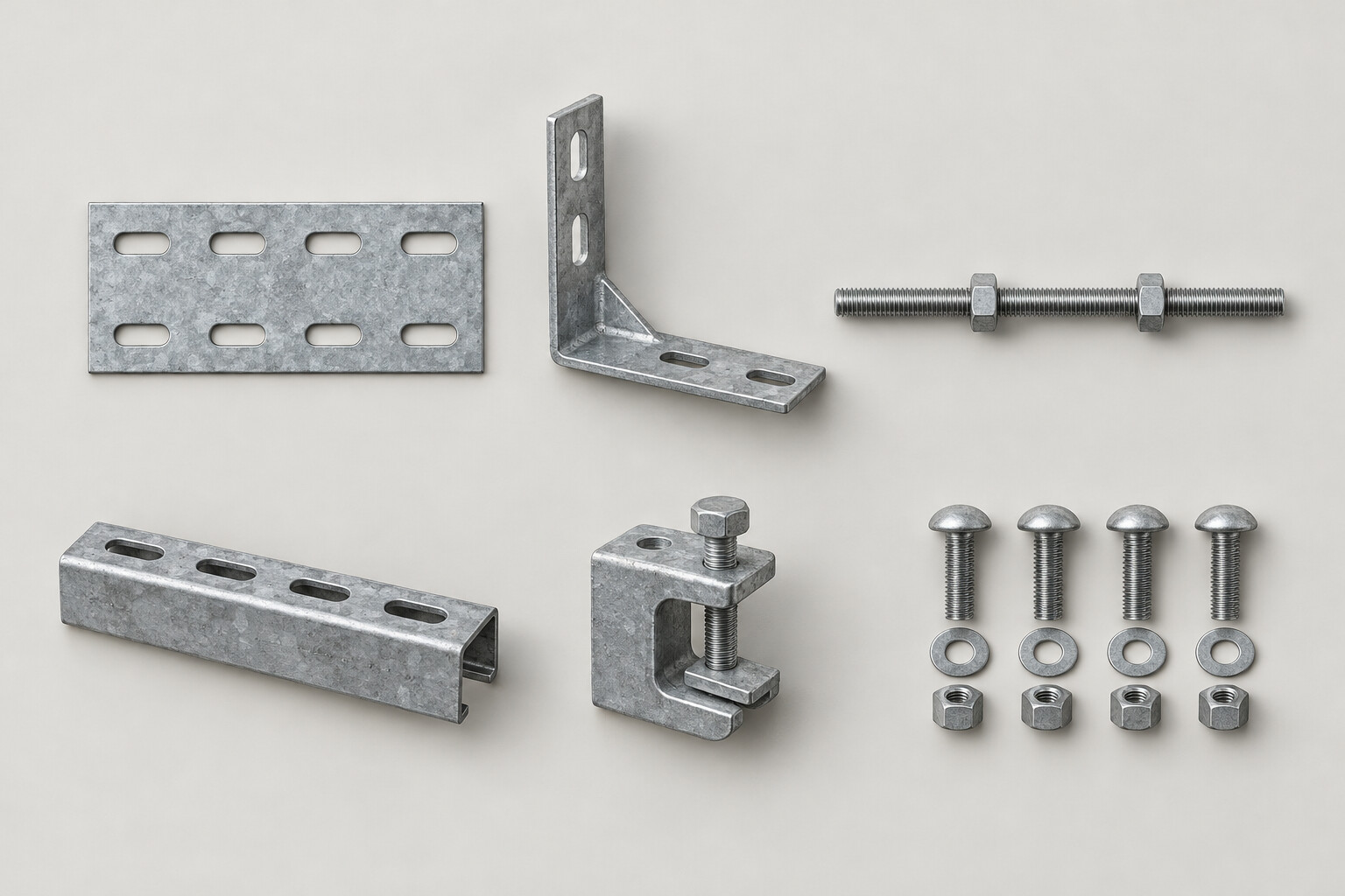
Short answer: cable tray installation starts with setting out the route and support points from the shop drawing. Then come the hanger rods, hanger beams or brackets, laying and splicing the tray with join sets, the fittings, locking the tray with hold down clamps and fitting the covers. A route is handed over only after straightness, support spacing, bolt tightness, electrical continuity at the joints and the condition of the finish have been checked.
If you are an EPC contractor or owner's engineer reviewing an installation subcontractor's method statement for a plant in Indonesia, this is the sequence to expect, and the checklist at the end is the one to inspect against.
The work sequence on one page
You can use this sequence directly as the outline of a method statement or JSA (job safety analysis). Each step is explained in the sections that follow.
- Review the approved shop drawing and compare it with site conditions.
- Receive and inspect the material: type, size, plate thickness, finish and accessory quantities.
- Set out the route centreline, elevation and support points on the ceiling, wall or structure.
- Install anchors and hanger rods, or brackets for wall-mounted routes.
- Install the hanger beams and adjust their elevation.
- Lay the straight tray and connect each length to the next with join sets.
- Install fittings at every bend, branch, change of width and change of elevation.
- Lock the tray to the supports with hold down clamps, and fit separators and end plates where required.
- Pull and tie the cables, then fit covers and cover clamps on covered routes.
- Carry out the final inspection, close out the findings, then hand over.
Preparation before working at height
Documents and material inspection
Start from the shop drawing approved by the consultant or the owner. Walk the route with the drawing in hand and look for clashes with ductwork, sprinkler pipes, beams and other trays. A clash found before setting out is far cheaper to resolve than one found after the hangers are in.
When material arrives on site, check it against the packing list and the BOQ. Check the type (type U or type C for cable tray; type U, type W or heavy duty for cable ladder), width and height, plate thickness, finish, and the quantities of join sets, fittings, covers and bolts. The standard length is 3,000 mm, so the number of lengths is easy to work out from the route length.
Tools required
- Tape measure, string line and laser level or spirit level for setting out and alignment.
- Drill and bits for anchors in concrete or steel.
- Ring, open-end or socket spanners to suit the join set and hanger rod bolts.
- Cut-off grinder and file for cutting tray and deburring cut edges.
- Zinc rich paint for touching up cut edges on HDG tray.
- Scaffolding or an aerial work platform, full body harness and standard PPE.
Safety points for the JSA
Most cable tray work is work at height with heavy steel material that has sharp edges. In the JSA, list the main hazards: falls from height, falling material or tools, cuts from plate edges, grinding sparks and electrical hazards when working near live panels. For each hazard, state the control: a suitable work platform, harness, barricaded area below, gloves, safety glasses and an electrical isolation procedure.
Setting out the route and support points
Mark the route centreline on the ceiling or structure with a laser or string line, then mark the elevation of the underside of the tray. Next, mark the support points. As a general guide, support spacing is 1.5 to 2 m for cable tray with a 50 mm height, 2 to 2.5 m for cable tray with a 100 mm height, and 2.5 to 3 m for cable ladder.
Do not simply divide the route length evenly. The joints and fittings decide where supports go:
- A support within 600 mm of every join set splice.
- A support on both sides of every elbow, tee and cross.
- On vertical runs, a support every 1.5 to 2 m.
The reasoning and the full table are in our article on cable tray support spacing. If the cable load is heavy and the span cannot be shortened, discuss it with the engineer before setting out, not after the tray shows deflection.
Installing supports: hanger rods, hanger beams and brackets
For suspended routes, fix anchors at the marked points and install two M10 hanger rods per point. Hang the hanger beam on the lower ends of the two rods and tighten the upper and lower nuts. Adjust the nuts until the hanger beam is at the marked elevation, then check with a laser or string line along the whole route before lifting the tray.
For routes on walls or columns, install support brackets with anchors suited to the wall material. Make sure the brackets are perpendicular to the wall and parallel to each other, because a bracket out of line will twist the tray.
Install all supports for one segment first, then lift the tray. Adjusting the elevation of hangers that already carry tray is much harder and more dangerous.
Laying and splicing the tray with join sets
Start from one fixed end, usually the panel or the first fitting, and work towards the other end. Lay the straight tray on the hanger beams, butt its end against the next length and fit join sets on both sides.
The joint holes are 10 x 14 mm slots at 25 and 50 mm from the end of the length. Insert all join set bolts hand-tight first, check that the two lengths are straight and level, then tighten all the bolts. Place the bolt heads on the inside of the tray so they do not damage the cable jackets during pulling.
A 30 m straight run with 3 m lengths needs 10 lengths and 9 join sets, plus join sets at each end of every fitting. The function of each component is listed in our article on cable tray accessories.
Cutting tray on site
When the remaining length is not a full 3,000 mm, cut the tray square to the centreline, deburr the edges with a file and drill new joint holes if needed. On hot dip galvanized tray, the cut edge loses its zinc coating, so apply zinc rich paint after cutting.
Installing fittings
Install a fitting at every change of direction and size:
Site condition | Fitting to install |
|---|---|
Flat 90 degree bend | Horizontal elbow, radius or diagonal |
Three-way branch | Tee |
Four-way branch | Cross |
Change in route width | Reducer (center, left hand or right hand) |
Rise or drop in elevation | Inside riser or outside riser |
Bend at an angle other than 90 degrees | Adjustable horizontal or vertical |
Fittings connect to the straight tray with the same join sets. Remember the rule of a support on both sides of each fitting: fittings are not designed to hang unsupported between two straight lengths. All fittings are listed on the accessories and supports page.
Locking the tray, pulling cable and fitting covers
Once a segment is spliced and straight, lock the tray to every hanger beam or bracket with hold down clamps. The clamps stop the tray from shifting when cable is pulled or when the structure vibrates. Fit a straight separator where power and control cables share one tray, and an end plate at the end of the route.
Pull cable only after the route is complete and checked. Tie the cables to the tray base or to the ladder rungs. On vertical cable ladder runs, cleat the cables to the rungs every 300 to 600 mm so the cable weight does not hang on the terminations.
Fit covers and cover clamps last, once the cables are dressed. Covers fitted before cable pulling will only have to be removed again. On covered outdoor routes, provide small drainage holes at the lowest point where there is a risk of water being trapped.
Inspection before handover
Use this table as the inspection checklist with the supervisor or consultant:
Item | How to check | Acceptance |
|---|---|---|
Route and elevation | Compare with the shop drawing | As drawn or as per approved changes |
Straightness | Laser or string line along the route | No unplanned bends or kinks |
Support spacing | Measure between hangers | As planned, with supports near joints and on both sides of fittings |
Deflection | Look and measure at mid span | No visible deflection, joints do not fold like a hinge |
Join set bolts | Visual check and random tightness test | Every hole has a bolt, nuts tight |
Hold down clamps | Check at every support | Installed and locking the tray |
Joint continuity | Per the grounding requirements in the specification | Joints electrically connected as per project specification |
Finish | Check cut edges and scratches | HDG cut edges painted with zinc rich paint |
Covers | Check on covered routes | Complete, with cover clamps |
Cleanliness | Check inside the tray | Free of loose bolts, plate offcuts and debris |
Record findings in a punch list, fix them, then re-inspect the flagged items. Attach photos of the route and the as-built drawing to the handover certificate.
Common mistakes on site
- Supports spaced evenly without regard to the joints. Joints end up at mid span and become weak points.
- Fittings without supports. Elbows and tees sag and pull on the adjacent lengths.
- Incomplete join set bolts. Empty holes weaken the joint and compromise continuity.
- HDG cut edges left untreated. Rust starts at the cut edge and spreads.
- Tray width sized too tight. There is no room for future cables. Confirm the required width before ordering; send your cable schedule via the contact page if you want it checked.
Have the material ready before installation starts
Installation runs smoothly when the tray, fittings and accessories arrive complete and match the drawings. Send your shop drawings, BOQ or cable schedule through the contact page. We prepare a complete quotation covering tray, fittings, join sets, supports and bolts, and can help calculate the support quantities from your layout.
Frequently asked questions
What tools are needed to install cable tray?
The basic tools are a tape measure, a string line or laser level, a drill for anchors, ring or socket spanners for the bolts, and a cut-off grinder and file. Also have zinc rich paint ready for cut edges on HDG tray. Work at height requires scaffolding or an aerial work platform, a full body harness and PPE.
In what order are the hangers and join sets installed?
Install and adjust all hangers in one segment first until their elevation is level. Then lay the tray, fit the join sets with hand-tight bolts, check the alignment and tighten all bolts. Finally, lock the tray to the hangers with hold down clamps.
What should be checked before a cable tray route is handed over?
Check the route and elevation against the shop drawing, straightness, support spacing, deflection, and that all join set bolts and hold down clamps are in place. Also check joint continuity against the project's grounding requirements, touch-up of HDG cut edges, completeness of covers and cleanliness inside the tray.
Can cable tray be cut on site?
Yes, provided it is cut square, the edges are deburred and joint holes are drilled again where needed. On hot dip galvanized tray, apply zinc rich paint to the cut edge, because the zinc coating is lost there.
When should cable tray covers be installed?
Covers go on last, after the cables have been pulled, tied and inspected. Secure the covers with cover clamps so they do not shift or come loose from vibration.