
Technical guides · 1 November 2026 · 7 min read
Cable tray elbows, tees and risers: choosing fittings and supports
Use an elbow for a 90° horizontal turn, a riser to go up or down in elevation, a tee or cross for branches and a reducer to change width. Install a support on both sides of every fitting.
Written by the Ponggawa technical team
Also available in: Bahasa Indonesia · 简体中文
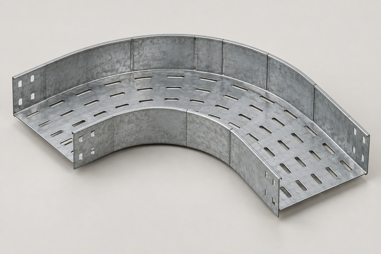
Short answer: every change of direction on a cable tray or cable ladder route uses its own fitting: an elbow for a 90° horizontal turn, an inside or outside riser to go up or down in elevation, a tee or cross for branches, and a reducer to change width. Install a support on both sides of every elbow, tee and cross, and within 600 mm of every joint. On a vertical run after a riser, install a support every 1.5 to 2 m and tie the cables to the rungs or the tray base.
Why changes of direction belong in the drawings
Straight runs are easy to take off: divide the length by 3,000 mm per section, and the number of join sets and supports follows. The problems usually appear at turns, branches and changes in elevation. At those points the drafter has to choose the right fitting, the estimator has to add lines to the BOQ, and the installer has to know where each support goes.
A fitting that is not in the drawings is not in the BOQ either, and the missing line only shows up when material arrives on site. For that reason, mark every change of direction on the layout drawing before the BOQ is prepared.
A fitting for every change of direction
The table below summarizes the fittings available for cable ladder and perforated cable tray, based on the product data.
Change of direction | Fitting | Cable ladder | Perforated cable tray |
|---|---|---|---|
90° horizontal turn | Elbow | Horizontal elbow (radius or diagonal model) | Tray elbow (radius or diagonal model) |
Three-way branch | Tee | Horizontal tee (radius or diagonal model) | Tray tee |
Four-way branch | Cross | Horizontal cross | Tray cross |
Change of width | Reducer | Reducer (center, left hand or right hand) | Straight reducer or offset reducer (left and right) |
Up or down in elevation | Inside and outside riser | 90° turn up or down | Radius or diagonal model |
Angle other than 90° | Adjustable vertical and horizontal | Variable-angle joint | Variable-angle joint |
For angle changes, fish plates are also available: horizontal and vertical joints for changes in angle. All of these joints are listed on the accessories and supports page.
Elbow: horizontal turns
Use an elbow when the route turns 90° in the horizontal plane, for example from a corridor into a panel room. Choose the radius or diagonal model to suit the minimum cable bending radius set by the electrical designer. Large cross-section power cables need more room to bend, so state the selected model on the drawing so that it is not mixed up at ordering.
Riser: going up and down in elevation
A riser is the fitting for a change in elevation, for example where the route drops from ceiling level to a panel or rises from a trench to a cable rack. Risers come in two types, inside riser and outside riser. The direction of the bend at each point decides which type is used, so mark the up or down direction on the section drawing and state the riser type for each point in the BOQ.
The difference from a simple elbow: an elbow turns the route in the horizontal plane, a riser turns it up or down. On cable ladder both are 90° fittings, but an elbow and a riser cannot replace each other.
Tee and cross: branches
A tee splits the route three ways, a cross four ways. For cable ladder, the horizontal tee is available in a radius or diagonal model. Tees and crosses go at the points where the main route branches off to a panel or another area.
Reducer: changing width
A reducer narrows the route. One example is after a branch, when some of the cables have left for the branch and fewer cables remain on the main route. Recalculate the width after every branch, then decide whether the route really needs to narrow. Include the cable schedule with your quotation request.
Cable ladder reducers are available as center, left hand or right hand. For cable tray, the options are a straight reducer or an offset reducer (left and right). Choose the type to suit the position of the continuing route on the layout drawing.
Support positions near fittings
Fittings add joints, and every joint needs support. The rules in the cable tray support spacing guide also apply around changes of direction.
Location | Support rule |
|---|---|
Join set joint | Support within 600 mm of the joint |
Elbow, tee and cross | Support on both sides of the fitting |
Every fitting | Support within 600 mm of the fitting |
Vertical run after a riser | Support every 1.5 to 2 m, cables tied to the rungs or base |
Vertical cable ladder | Cables clamped to the rungs every 300 to 600 mm |
For straight runs between fittings, typical support spacing is 1.5 to 2 m for 50 mm high cable tray, 2 to 2.5 m for 100 mm high cable tray, and 2.5 to 3 m for cable ladder. The final spacing depends on cable weight and plate thickness.
On a vertical run, the cable load no longer rests on the base or rungs as it does on a horizontal run. That is why the cables are clamped at the intervals above, so their weight does not hang from the termination end.
Fittings for cable duct, raceway and wire mesh tray
Other systems have their own fitting rules:
- Cable duct: elbow and elbow 90 for horizontal turns, equal tee and equal cross for fully covered branches, outside and inside riser for changes in elevation.
- Raceway: elbow and elbow 90, equal tee and equal cross, inside and outside riser, plus a hanger support for suspending from the ceiling.
- Wire mesh tray: turns, tees and reducers are formed on site by cutting some of the wires and joining them with clamps, without prefabricated fittings.
Steps to build the fitting list from the drawings
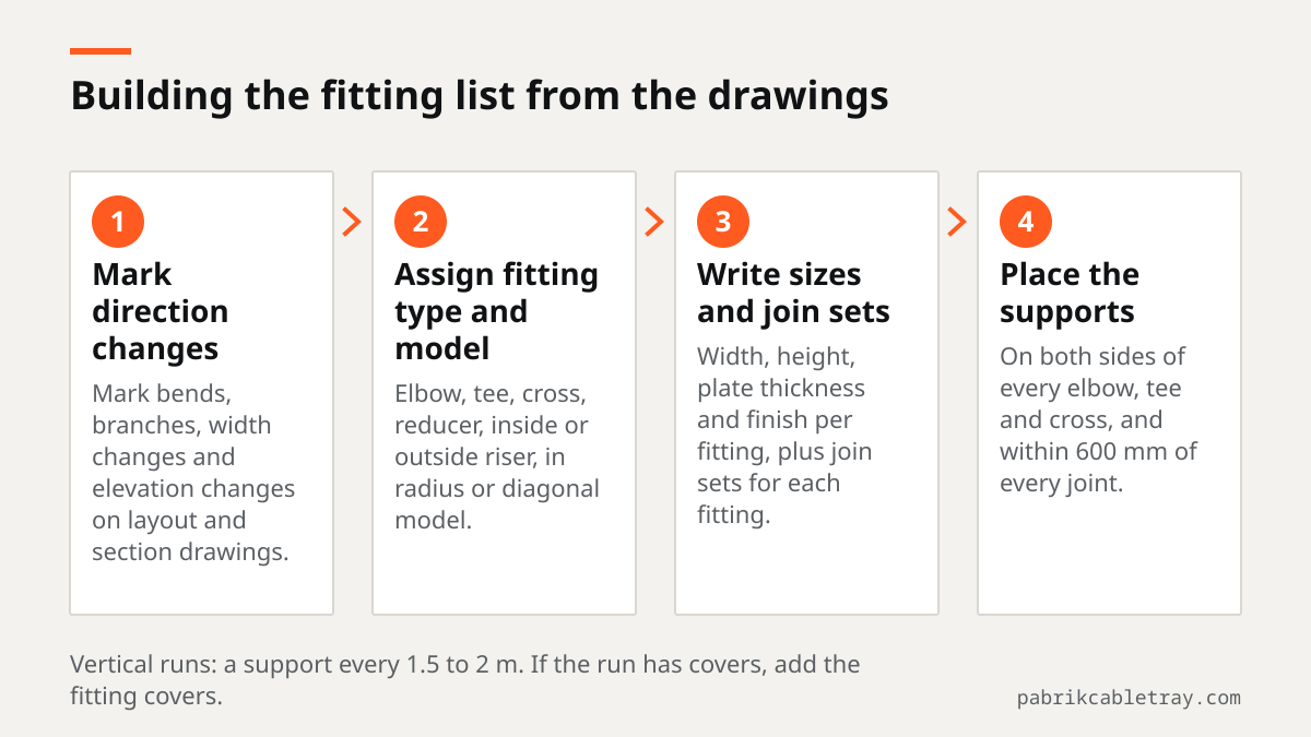
- Mark every horizontal turn, branch, change of width and change of elevation on the layout and section drawings.
- Assign a fitting type to each point: elbow, tee, cross, reducer, inside riser or outside riser, with its model (radius or diagonal, center or offset).
- Write the width, height, plate thickness and finish for each fitting, the same as for the straight section lines in the BOQ.
- Add join sets for the joints at every fitting, in addition to the join sets between straight sections.
- Place supports on both sides of every elbow, tee and cross, within 600 mm of every joint, and every 1.5 to 2 m on vertical runs.
- If the route has covers, add the matching fitting covers: elbow, tee, cross, reducer and riser covers. Guidance on choosing covers is in the article when a cable tray needs a cover.
Other lines that are often missed, such as hold-down clamps and end plates, are covered in cable tray accessories for the project BOQ.
Request a quotation with a complete fitting list
Send your layout and section drawings, BOQ or cable schedule through the contact page. State the system type, size, plate thickness, finish and project location. The Ponggawa team prepares a quotation per project, including the fittings, join sets and supports at every change of direction, and can help calculate the support requirement from your drawings.
Frequently asked questions
What is the difference between an elbow and a riser?
An elbow is a 90° horizontal turn, used where the route turns in the horizontal plane. A riser is a turn up or down for a change in elevation, available as an inside riser and an outside riser. The two cannot replace each other, so state the type for each point in the BOQ.
When should I use a reducer?
Use a reducer when the route width needs to change, for example after a branch when fewer cables remain on the main route. Recalculate the width before you decide. Cable ladder uses a center, left hand or right hand reducer, and cable tray uses a straight reducer or an offset reducer (left and right).
How should supports be spaced near a turn?
Install a support on both sides of every elbow, tee and cross, and within 600 mm of every joint and fitting. On straight runs between fittings, follow the typical support spacing for the tray type and height. The final spacing depends on cable weight and plate thickness.
How do I install cable ladder on a vertical run?
Use an inside or outside riser for the change of direction from horizontal to vertical. Install a support every 1.5 to 2 m on the vertical run, then clamp the cables to the rungs every 300 to 600 mm. This way the cable load does not hang from the termination end.
What if the turn is not 90°?
Use an adjustable vertical or horizontal fitting, which is a variable-angle joint. Fish plates are also available as horizontal and vertical joints for angle changes. State the required angle on the drawing so that the joints delivered match it.