Pricing and budgeting · 29 October 2026 · 9 min read
Cable tray accessories in a BOQ: the line items that get missed
Besides straight tray, a BOQ needs separate lines for fittings, join sets and bolts, supports, hold down clamps, covers with cover fittings and cover clamps, separators and end plates.
Written by the Ponggawa technical team
Also available in: Bahasa Indonesia · 简体中文
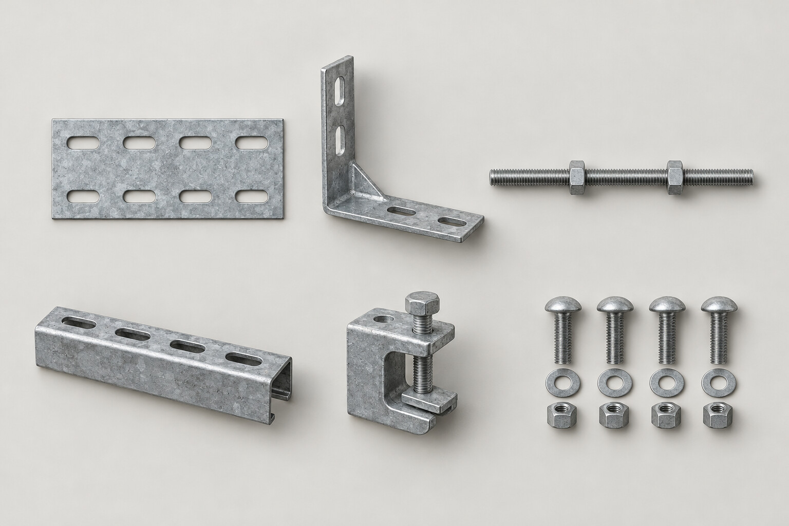
Short answer: A complete cable tray accessories BOQ separates straight tray from fittings (elbow, tee, cross, reducer, riser), join sets and bolts, supports (hanger beam or bracket with M10 hanger rod), hold down clamps, covers with cover fittings and cover clamps, straight separators and end plates. Each line states width, height, finish and unit, and the quantity is counted from the route drawings, not taken as a percentage of tray length.
Why cable tray accessories need their own BOQ lines
Picture a cable route BOQ with a single line: "cable tray 300 x 100, so many meters". That line covers the straight tray, but it does not say how many elbows, how many join sets or how many support points the route needs. A supplier quoting from a line like that has to guess, and the guesses of two suppliers can be far apart.
Accessories that are not written into the BOQ can turn up later as variation work, even though all of them can be counted as soon as the layout drawing is complete. A BOQ that separates each type of accessory also lets your procurement team compare quotations line by line.
The function of each component is explained in the article on cable tray accessories and their functions. This article focuses on how to write them as BOQ lines.
BOQ checklist for cable tray accessories
The table below summarizes the lines needed for one cable tray or cable ladder route, the data each line must state and its unit.
BOQ line | Data to state | Unit |
|---|---|---|
Straight tray or ladder | Type, width x height, plate thickness, finish | 3 m length |
Elbow | Width x height, model (radius or diagonal) | pcs |
Tee | Width x height, model (radius or diagonal) | pcs |
Cross | Width x height | pcs |
Reducer | Start and end width, model (center, left or right) | pcs |
Inside and outside riser | Width x height, direction (up or down) | pcs |
Join set | Rail or side height (H) | set |
Bolts and nuts | Size 3/8 x 3/4 inch, finish | set |
Hanger beam or bracket | Tray width (W) | pcs |
M10 hanger rod | Length per point | pcs |
Hold down clamp | Height (H) | pcs |
Straight cover | Width | 3 m length |
Cover fitting | Fitting type and width | pcs |
Cover clamp | To match the cover | pcs |
Straight separator | Height to match the tray, length of the separated run | per run length |
End plate | Width x height | pcs |
Fish plate or adjustable joint | Orientation (horizontal or vertical) | set |
State the finish on every line. On the accessories and supports page, the accessory finish is listed as following the tray finish, and bolts are available in HDG or electro galvanized.
Fittings: one line per type, size and model
Cable tray and cable ladder fittings consist of elbows, tees, crosses, reducers and inside and outside risers. Do not merge them into a single line such as "fittings, 1 lot". Each type has its own size and model, and the supplier needs the quantity of each.
Details that need to be written:
- Elbows and tees: model, radius or diagonal.
- Reducers: start width and end width, and the model. For cable ladder, the models are center, left hand or right hand. For cable tray, the models are straight reducer or offset reducer (left or right).
- Risers: list inside risers and outside risers separately, because they bend in different directions.
- Angles other than 90 degrees: elbows are made for 90 degree bends. For bends at any other angle, add a line for fish plates or adjustable vertical and horizontal joints, which are variable angle connections.
Join sets and bolts: counted per joint
One join set (a pair of splice plates with bolts) is used at every joint between lengths. Join sets are made per height, so state the rail or side height (for example join set H100) on the BOQ line.
The join set count does not stop at straight to straight joints. Every fitting end that meets a straight tray is also a joint. Count the ends from the drawing: an elbow has two ends, a tee three, a cross four.
Bolts go on a separate line. Each joint uses about 8 bolt sets, either carriage bolts or hexagon bolts 3/8 x 3/4 inch. The joint holes in tray and ladder are 10 x 14 mm slots.
Supports and hold down clamps: counted per point
The number of supports follows the number of points, not meters of tray. Typical support spacing is 1.5 to 2 m for 50 mm high cable tray, 2 to 2.5 m for 100 mm high cable tray, and 2.5 to 3 m for cable ladder. The details are in the article on cable tray support spacing.
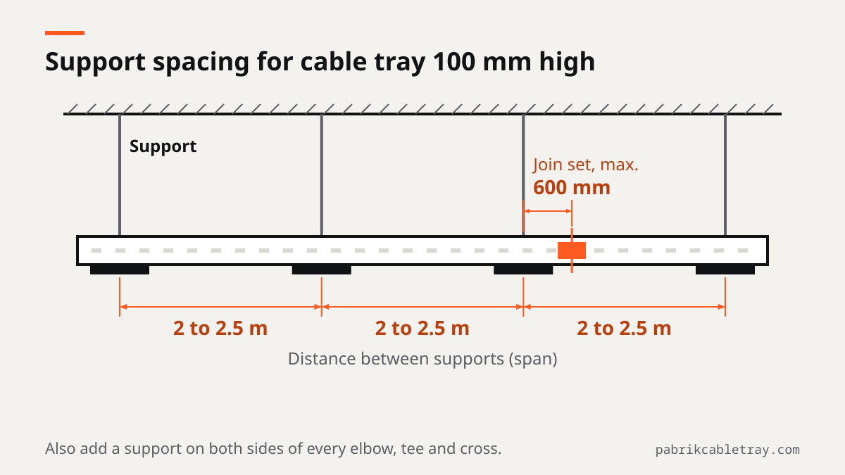
Besides the points along straight runs, add the following support points when counting from the drawing:
- A support within 600 mm of every join set joint.
- A support on both sides of every elbow, tee and cross.
- A support every 1.5 to 2 m on vertical runs.
Each suspended support point consists of 1 hanger beam and 2 M10 hanger rods. Points on a wall or column use a bracket. Hanger beams and brackets are ordered per tray width, so state the width.
M10 hanger rods are made to the length ordered. State the length per point, or at least the ceiling height and the tray elevation, so the supplier does not have to guess. The accessories list on the product page does not include anchors into concrete or steel, so make sure the anchor line is in another work package.
Hold down clamps lock the tray to the support. In the worked example below, each support point uses 2 hold down clamps. State the height, for example hold down clamp H100.
Covers, cover fittings and cover clamps
Covers are counted separately from straight tray, per 3 m length. When a route uses covers, the fittings on that route also need matching covers: elbow cover, tee cover, cross cover, reducer cover and riser cover. These cover fitting lines are easy to miss because the estimator only multiplies the route length.
Covers are secured with cover clamps, so add a cover clamp line for every covered route. The article when a cable tray needs a cover explains which routes need one.
Ancillary items: straight separators and end plates
These two lines are small in quantity, but their absence only shows during installation.
- Straight separator: divides power cables from control cables inside one tray. Count its length from the part of the route that carries both cable types.
- End plate: closes the end of a route. Count from the number of route ends that do not connect to another tray.
How to count accessories from the layout drawing
Follow this sequence so no line is missed.
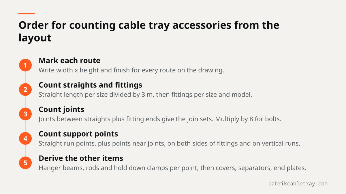
- Mark every route on the drawing with its width x height and finish.
- Measure the straight length per size, then divide by 3 m for the number of straight lengths.
- Count elbows, tees, crosses, reducers and risers per size and model, directly from the drawing.
- Count the joints: joints between straight lengths plus fitting ends that meet straight tray. The result is the number of join sets.
- Multiply the number of joints by 8 for bolts.
- Count the support points on straight runs according to the support spacing, then add points near joints, on both sides of fittings and on vertical runs.
- Derive hanger beams or brackets, hanger rods and hold down clamps from the number of support points.
- For covered routes, count straight covers, cover fittings and cover clamps.
- Add straight separators and end plates.
Example for a 30 m straight run with no bends, 3 m lengths and a support every 2 m. The support figures in this table are for the straight run only, that is the first part of step 6, before the extra points near joints:
Line | Quantity |
|---|---|
Straight tray | 10 lengths |
Join set | 9 sets |
Bolts (8 per joint) | 72 sets |
Support points, straight run | 16 points |
Hanger beam | 16 pcs |
M10 hanger rod | 32 pcs |
Hold down clamp | 32 pcs |
Straight cover (if the route is covered) | 10 lengths |
With supports at 0, 2, 4 and so on up to 30 m, some joints between lengths have no support within 600 mm. Check every joint on the drawing, add a support point near each joint that is not yet covered, then add a hanger beam, 2 hanger rods and 2 hold down clamps for each of those extra points. You can also shift the support positions so they fall near the joints, as long as the spacing stays within the support spacing limit.
The size pages on the Indonesian site carry a similar calculation for straight runs, for example cable tray 300 x 100. The available widths and heights are listed on the cable tray product page. To work out the tray width from a cable list, send the list through the contact page.
What makes accessory costs go up or down
Accessory cost is not proportional to route length. A short route with many bends and branches can need more fittings, join sets and supports than a longer straight route.
Factors that determine accessory cost:
- The number and type of fittings, and whether the fittings need covers.
- Tray width and height, because join sets, hold down clamps, hanger beams and brackets follow the size.
- Support spacing, which sets the number of points.
- Finish (HDG, electro galvanized or powder coating).
- Total quantity per size.
Send your BOQ or drawings for a complete quotation
Send your layout drawings, BOQ or cable schedule through the contact page. Ponggawa prepares a quotation per project from those documents, with straight tray and covers itemized separately. If your BOQ does not yet separate the accessories, send the layout drawings so the fittings, joints and supports can be counted from the routes.
Frequently asked questions
What is counted separately from the straight tray length?
Fittings (elbow, tee, cross, reducer, riser), join sets, bolts, supports (hanger beam or bracket with M10 hanger rod), hold down clamps, cover fittings, cover clamps, straight separators and end plates. All of these items are counted from the number of joints, support points, bends and route ends, not from meters of tray.
Do covers and join sets get their own BOQ lines?
Yes. Covers are counted separately from straight tray per 3 m length, and every fitting on a covered route uses a matching cover fitting. Join sets are also a separate line, one set for every joint, with the tray height stated on the line.
How do I estimate the number of fittings from the drawings?
Count each horizontal bend directly as an elbow, each three way branch as a tee, each four way branch as a cross, each change of width as a reducer and each change of elevation as an inside or outside riser. Group them by size and model. Then count the ends of each fitting to add to the join set count and to the support points on both sides.
Is the hanger rod already included in the support line?
It is better written as a separate line. Each suspended support point uses 2 M10 hanger rods, and they are made to the length ordered, so the BOQ needs to state the length per point or the ceiling height and the tray elevation.
Can accessories be written as a percentage of the tray price?
A percentage makes quotations hard to compare, because the accessories needed depend on the number of bends, joints and support points on the drawing. Count each line from the layout, then ask suppliers to itemize the price per line in their quotations.