Technical guides · 21 October 2026 · 9 min read
Cable ladder load capacity: how to read load test results and span
Cable ladder load capacity depends on the support span and the deflection limit. A type W ladder, 1,000 x 100 mm with 2.0 mm plate, carries 360 kg at the 10 mm deflection limit on a 2.5 m span.
Written by the Ponggawa technical team
Also available in: Bahasa Indonesia · 简体中文
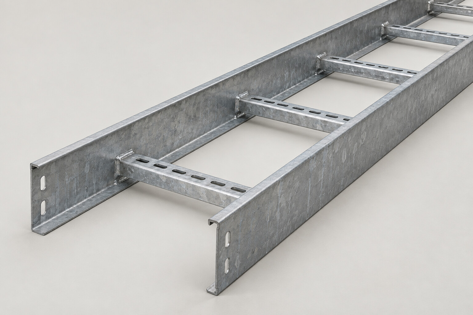
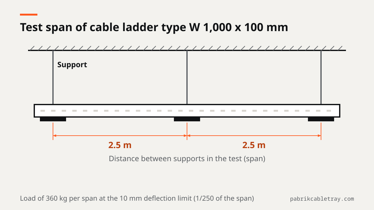
Short answer: cable ladder load capacity is only meaningful together with the support span and the deflection limit; it is never a single standalone figure. For example, an independent laboratory load test report for a type W cable ladder, 1,000 mm wide, 100 mm high, with 2.0 mm plate on a 2.5 m span, records 360 kg exactly at the 10 mm deflection limit (1/250 of the span, NEMA VE 1 class 10A). That figure applies only to this configuration, so other sizes and other spans need their own calculation.
When you write a cable ladder specification or review a supplier's data for a plant in Indonesia, ask for all three numbers together: test span, deflection limit and load at that limit. This guide shows how to read them and how to check them against your own cable routes.
What cable ladder load capacity means
On site, the question "how many kg can this ladder take?" is often answered with one number. The problem is that the number means nothing without two other details: the distance between supports used in the test, and the deflection accepted as the limit.
A cable ladder works like a simply supported beam. The two side rails carry the cable load resting on the rungs and transfer it to the hangers or brackets. The longer the distance between supports, the larger the deflection for the same load. That is why cable ladder load capacity is always stated as "so many kg on a span of so many meters with a maximum deflection of so many mm".
The NEMA VE 1 standard defines this test method. The tray or ladder is mounted on a set span, loaded uniformly, and its deflection is measured. Based on the result, the ladder is assigned a load class, for example class 10A.
Three numbers to read together
Every load test result that is fit for design use contains the following three numbers.
Number | Meaning | Example from the type W test |
|---|---|---|
Test span | Distance between the two supports during the test | 2.5 m |
Deflection limit | Maximum deflection allowed at working load | 10 mm (1/250 of the span) |
Load at the deflection limit | Load that produces deflection exactly at the limit | 360 kg per span |
If one of the three is missing, the test result cannot be compared with the project requirement. A figure of 360 kg without the span can be too optimistic for a route with hangers spaced further apart.
What the 1/250 span deflection limit means
A 1/250 limit means the deflection at midspan must not exceed the span length divided by 250. On a 2.5 m span, or 2,500 mm, the limit is 10 mm. This limit keeps the route visually straight, stops the join set connections from acting like hinges, and prevents cables from being pulled at the support points.
Deflection rises much faster than the span grows. Lengthening the hanger spacing even slightly can push deflection past the limit, even with the same cable load. This is why support spacing must not be widened casually just to save on hangers.
Reading the type W 1,000 x 100 mm test example
The cable ladder products we supply have a load test report from an independent laboratory, made by our partner manufacturer in Bekasi. The report covers a type W cable ladder in the following configuration:
- Width 1,000 mm, rail height 100 mm, plate thickness 2.0 mm.
- Test span 2.5 m.
- Load of 360 kg exactly at the 10 mm deflection limit, or 1/250 of the span.
- NEMA VE 1 class 10A classification.
- The sample still carried load up to 550 kg per span.
How to read it: 360 kg is the figure relevant for design, because at that load the deflection is still within the allowable limit. The 550 kg figure shows the strength reserve of the sample beyond the deflection limit. It is not a working load, so do not use it to calculate cable fill.
Widths, rail heights and fittings for the cable ladder range are listed on the cable ladder product page.
What counts as load
The load on a ladder is not only the weight of the cables installed today. Include everything the ladder supports within that span:
- Cable weight per meter from the cable datasheet, multiplied by the number of cables and the span length.
- Covers, straight separators and other accessories attached to the ladder.
- Additional cables planned for later project phases.
Main routes can fill up faster than planned. Leaving load margin at the design stage costs less than adding hangers after the cables are pulled.
Does a test result for one size apply to all sizes
No. Actual capacity depends on width, rail height, plate thickness and support spacing. The test result for a type W 1,000 x 100 mm ladder with 2.0 mm plate on a 2.5 m span represents that configuration only.
Some situations where the test result cannot be applied directly:
- A ladder with 1.8 mm plate, even if the width and height are the same.
- A type U ladder, because its side rail profile is different and more flexible than type W at the same plate thickness.
- Hanger spacing longer than 2.5 m, because deflection rises sharply.
- Heavy duty rails (127 mm or 152 mm), which have a different stiffness.
For any configuration other than the one tested, ask for a calculation based on your project's span and cable load. Do not scale the 360 kg figure proportionally to other sizes, because the relationship between dimensions, span and deflection is not linear.
Choosing type U, type W or heavy duty by load
The choice of ladder type should start from the cable load per span and a realistic support spacing on site. A summary from the product data:
Type | Side rail profile | Rail height | When to use |
|---|---|---|---|
C profile with inward lip | 50 and 100 mm | General indoor and outdoor routes, commercial buildings, factories, panel rooms | |
Type W | W profile, double folded, stiffer | 100 mm | Dense power cabling, hanger spacing that cannot be reduced, pipe racks |
High rail | 127 and 152 mm | Long spans, heavy medium voltage cables, smelters, power plants, oil and gas |
The W profile adds extra folds to the side rail, which raises its moment of inertia. The result is lower deflection on the same span than a type U ladder with the same plate thickness. The full explanation is in the article on cable ladder type U vs type W.
The reasoning goes roughly like this. If the cable load is light to medium and hangers can be installed close together, type U is usually enough. If the load is heavy but the hanger spacing is fixed by the structure, step up to type W. If spans are long and cable layers are deep, consider heavy duty.
Steps to check load capacity on a project
- Set a realistic support spacing from the structural drawings, for example the beam spacing, pipe rack column spacing or suspension points on the floor slab.
- Calculate the cable load per meter from the cable datasheets and the number of cables per route, then add covers, separators and spare cable capacity.
- Multiply the load per meter by the span to get the load per span.
- Set the deflection limit required by the project specification, usually 1/250 of the span, and the NEMA VE 1 load class if one is specified.
- Compare with the test data or calculation for the selected type, width, rail height and plate thickness.
- If it does not fit, reduce the support spacing, increase the rail height, or move to type W or heavy duty.
- Check the details at the joints: install a support within 600 mm of each join set and on both sides of every fitting, as described in the guide to cable tray support spacing.
The ladder width itself is set by the number and diameter of cables. For that step, see cable tray sizing, then return to the load check above.
The products we supply are made from hot rolled sheet steel SPHC, 1.8 to 2.0 mm thick (other thicknesses to order), with a design based on NEMA VE 1, by a partner manufacturer in Bekasi certified to ISO 9001:2015. The background is explained on the About Ponggawa page.
If you are preparing a specification or a BOQ for an EPC package or your own plant, send the layout drawings, cable schedule and planned support spacing through the contact page. We match the ladder type, rail height and plate thickness to the span and load class you require, then prepare the quotation.
Frequently asked questions
How much load can a cable ladder carry?
It depends on width, rail height, plate thickness and support spacing. As a reference, a type W cable ladder 1,000 mm wide, 100 mm high, with 2.0 mm plate on a 2.5 m span carries 360 kg exactly at the 10 mm deflection limit, according to an independent laboratory test report. For other sizes and spans, send your data for a calculation.
What does a deflection limit of 1/250 of the span mean?
The deflection at midspan must not exceed the span length divided by 250. On a 2.5 m span, the limit is 10 mm. This keeps the route straight, the joints rigid and the cables free of tension at the support points.
Does a load test result for one size apply to all sizes?
No. A test result represents only the type, width, rail height, plate thickness and span that were tested. A ladder with thinner plate, a different rail profile or wider hanger spacing needs its own calculation.
How do I choose between type W and type U based on load?
Start from the cable load per span and the support spacing that can be installed on site. Type U is enough for light to medium loads with closely spaced hangers. Choose type W for dense power cabling where hanger spacing cannot be reduced, because the W profile is stiffer at the same plate thickness.
Can the 550 kg figure be used as a working load?
No. The 550 kg figure shows the load the sample still carried beyond the deflection limit, so it is a strength reserve. For design, use the load at the deflection limit, which is 360 kg for the tested configuration.