Technical guides · 28 October 2026 · 8 min read
Cable tray and cable ladder plate thickness for specs and BOQs
Ponggawa cable tray and cable ladder use SPHC steel plate of 1.8 to 2.0 mm, with other thicknesses to order. In the BOQ, state the thickness per component together with size, finish and load class.
Written by the Ponggawa technical team
Also available in: Bahasa Indonesia · 简体中文
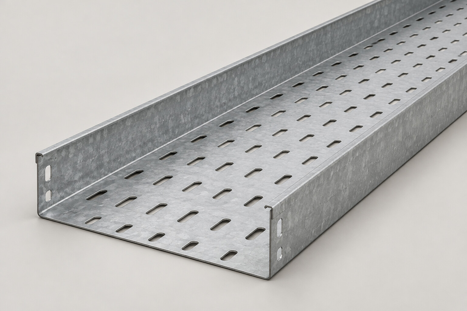
Short answer: the cable tray and cable ladder supplied by Ponggawa are made from 1.8 to 2.0 mm hot rolled sheet steel SPHC, and other thicknesses can be made to order. In your specification and BOQ, state one thickness in mm for each component, together with the type, width, rail height, finish and the load class or support spacing. That way the quotation and the material delivered to site can be checked against the same figure.
Cable tray and cable ladder plate thickness in the product data
This table summarizes the material data for the cable tray and cable ladder we supply. The same figures appear in our quotation, so the project QC team can use them when the material arrives.
Item | Product data |
|---|---|
Material | Hot rolled sheet steel (SPHC) |
Cable tray and cable ladder plate thickness | 1.8 to 2.0 mm, other thicknesses to order |
Cable duct cover thickness | 1.2 mm |
Standard length | 3,000 mm per length |
Finish | Hot dip galvanized (BS 729, DIN 50976), electro galvanized, powder coating |
Design reference | NEMA VE 1 |
The 1.8 to 2.0 mm range is product data, not a limit that binds every project. If the project technical specification calls for a different thickness, that thickness can be ordered. Product details are on the cable tray and cable ladder pages.
Keep in mind that one system consists of several components. The cable duct cover, for example, is 1.2 mm thick, which differs from the tray body. A single line such as "2 mm thick" that does not name the component can therefore be read differently by the drafter, the estimator and the supplier.
What changes when the plate is thicker
A thicker plate changes three things that show up directly on the project.
- Stiffness. Rails and bases made from thicker plate deflect less under the same load and span.
- Weight per length. Each 3,000 mm length becomes heavier, so the dead load carried by supports and hangers increases, and so does the lifting work during installation.
- Cost. Plate thickness is one of the cost factors, together with width, height, finish, number of fittings and quantity. For cost figures, ask for a quotation based on your BOQ.
In other words, a thicker plate is not free. Before you write a larger figure into the specification, make sure plate thickness is really what needs to change.
Plate thickness is not the only way to add capacity
Cable ladder capacity depends on width, rail height, plate thickness and support spacing. So when the load calculation does not work out, there are several routes you can compare.
- Rail shape. Cable ladder type W uses a double folded side rail, which raises its moment of inertia. It deflects less at the same span than type U with an equivalent plate thickness, so type W is used for heavier cable loads without adding plate thickness.
- Rail height. Heavy duty cable ladder uses 100 to 152 mm rails for large power cables and long spans, with extra stiffness from the rail height and a reinforcing lip or flange.
- Tray side wall profile. For cable tray, type C folds the side wall into a C profile, so the top edge is stiffer. Consider type C for widths of 400 mm and above or for longer support spans.
- Support spacing. Closer supports reduce deflection without changing the product, but they add hangers.
- Plate thickness. Thicknesses outside 1.8 to 2.0 mm can be ordered when the other options do not suit site conditions.
The project design engineer decides which combination to use. The supplier can help with the calculation when given the cable and span data.
How plate thickness affects support span
Plate thickness is one of the factors that set the support span. The final support spacing depends on cable weight and plate thickness. As a starting point, the cable tray support spacing guide uses the following general figures.
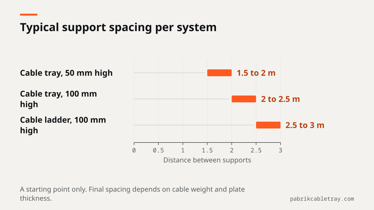
System | General support spacing |
|---|---|
Cable tray, 50 mm high | 1.5 to 2 m |
Cable tray, 100 mm high | 2 to 2.5 m |
Cable ladder, 100 mm high | 2.5 to 3 m |
For an indication of capacity in one real configuration, load test data is available. A type W cable ladder, 1,000 mm wide, 100 mm high, with 2.0 mm plate, was made by the partner manufacturer in Bekasi. An independent laboratory then tested it at a 2.5 m span. The result was 360 kg exactly at the 10 mm deflection limit (1/250 of the span, NEMA VE 1 class 10A), and the sample carried up to 550 kg per span.
These figures apply to that configuration only. Do not simply apply them to 1.8 mm plate, to type U or to another width. How to read this test result is covered in the article on cable ladder load capacity.
When to consider a thicker plate
The plate thickness decision should come from calculation, not from the habit of the previous project. The following sequence helps the design team reach a figure it can justify.
- Set the tray width and height from the number and diameter of cables. To size the width, send your cable list through the contact page.
- Calculate the cable weight per meter from the cable schedule, including any planned spare cables.
- Fix a support spacing that can actually be installed on site, for example on a pipe rack or above a service road where hangers cannot be placed closer together.
- Match it to the load class or the deflection limit the specification requires. A NEMA VE 1 load class is a combination of support span and working load per unit length.
- Compare the options if the calculation still does not work out, following the list in the section on adding capacity above.
- Write the result into the specification as a thickness per component, together with the load class or support spacing the calculation is based on.
If the project specification already states a thickness, follow that figure and list it in the BOQ. If it does not, send the span and cable weight data so the type, rail height and plate thickness can be matched to the required load class.
How to write plate thickness in the specification and BOQ
Misunderstandings about plate thickness can start with a BOQ line that is too short. The following four habits close the gap.
- One figure per item. Write "plate thickness 2.0 mm", not "1.8 to 2.0 mm". A range in the BOQ makes two quotations hard to compare.
- Name the component. Separate the thickness of the tray body or ladder rail from the thickness of the cover. For fittings such as elbows, tees and risers, state the required thickness and finish rather than assuming them.
- Keep plate thickness separate from the finish coating. A clean specification lists material and plate thickness as one item, then the finish and, for HDG, the zinc coating thickness as another. Also agree whether the plate thickness figure means the steel before or after finishing.
- Link it to the design basis. State the required NEMA VE 1 load class or support spacing, so the supplier knows which conditions the thickness figure is meant for.
Example BOQ lines:
No | Description | Unit |
|---|---|---|
1 | Cable ladder type W, W 600 x H 100 mm, length 3,000 mm, material SPHC, plate thickness 2.0 mm, hot dip galvanized, NEMA VE 1 class as per specification | length |
2 | Horizontal elbow 90° for cable ladder type W, W 600 x H 100 mm, plate thickness and finish same as item 1 | pc |
3 | Perforated cable tray type U, W 300 x H 100 mm, length 3,000 mm, material SPHC, plate thickness 2.0 mm, hot dip galvanized | length |
4 | Cable tray cover W 300 mm, thickness and finish as per specification | length |
The choice of finish itself is covered in the article HDG or electro galvanized.
Checking plate thickness when the material arrives
Plate thickness, finish and reference standards are stated in our quotation, so they can be checked when the material arrives on site. Measure the thickness at the edge of a length with a caliper or micrometer, then compare it with the figure in the quotation and the BOQ.
On HDG tray, the zinc coating is included in a measurement taken at the edge. That is why the "before or after finishing" agreement in the BOQ matters, so site measurements do not lead to disputes.
Send your project layout drawings, BOQ or cable schedule through the contact page. We prepare a quotation with the type, rail height and plate thickness that suit the required load class, with the finish and reference standards clearly stated.
Frequently asked questions
What is the standard plate thickness for cable tray?
The cable tray and cable ladder supplied by Ponggawa use 1.8 to 2.0 mm SPHC plate. Other thicknesses can be made to order when the project specification requires them. The cable duct cover in our product data is 1.2 mm thick, so list the cover thickness as a separate item.
When do I need a plate thicker than 1.8 to 2.0 mm?
When the project specification calls for a specific thickness, or when the calculation of cable weight and support spacing does not yet meet the required load class. Before increasing the thickness, compare other options first, such as a type W rail, a heavy duty rail or closer supports. The project design engineer decides, and we can help with the calculation from your span data.
Does plate thickness affect the support span?
Yes. The final support spacing depends on cable weight and plate thickness, as well as on width and rail height. Independent laboratory load test data for a type W cable ladder, 1,000 x 100 mm with 2.0 mm plate, recorded 360 kg at the 10 mm deflection limit on a 2.5 m span, and that figure applies only to that configuration.
How should plate thickness be written in a BOQ?
Write one thickness in mm for each item, name the component (body, rail or cover), and keep it separate from the finish item. Add the material, type, width, height, length and the load class or support spacing the calculation is based on. Also agree whether the thickness figure means the steel before or after finishing.