Technical guides · 22 October 2026 · 8 min read
Cable tray grounding and bonding: what to write in the spec and BOQ
A tray splice does not automatically guarantee grounding. State the tray's role in the specification, how continuity is kept at every joint and where bonding jumpers go, then carry it into the BOQ.
Written by the Ponggawa technical team
Also available in: Bahasa Indonesia · 简体中文
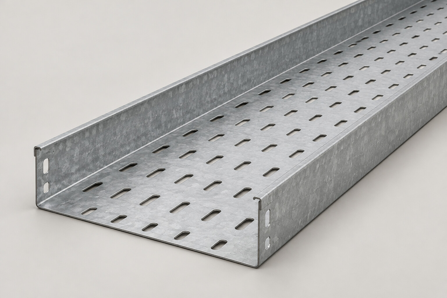
Short answer: grounding of cable tray and cable ladder depends on two decisions by the electrical designer: whether the tray is grounded only or is used as an equipment grounding conductor, and how electrical continuity is kept at every joint. Tightly fitted join sets on galvanized tray can carry current, but at expansion joints, adjustable joints, painted finishes and gaps in the route, the specification needs to call for bonding jumpers. Write all of this into the specification and the BOQ so that no item falls between the contractor and the supplier.
Two roles of the tray in the grounding system
A steel cable tray route is exposed metal close to energized cables. If cable insulation is damaged and touches the tray, the tray must have a path to ground so that the protection operates. For that reason a metal tray is grounded as well.
The question lies in the second role. Some projects use the metal tray itself as the equipment grounding conductor. Other projects run a separate grounding conductor along the tray and only bond the tray to that conductor. This decision belongs to the project's electrical designer, not to the tray supplier.
The difference matters a great deal for site work:
Role of the tray | What carries the fault current | What must be maintained |
|---|---|---|
Grounded only (not used as a conductor) | A separate grounding conductor along the route | The bond from tray to conductor at the points the designer sets |
Used as a grounding conductor | The tray body and all its joints | Electrical continuity at every joint, fitting and gap |
If the specification does not state the role, the contractor will guess. The result can be double work or, the other way around, a route without continuity that nobody knows about.
Is a join set splice enough?
On a straight run, two tray lengths are connected with a join set: a pair of splice plates with bolts. The products we supply use 10 x 14 mm joint slots and 3/8 x 3/4 inch bolts, available in HDG or electro galvanized finish. Details are on the accessories and supports page.
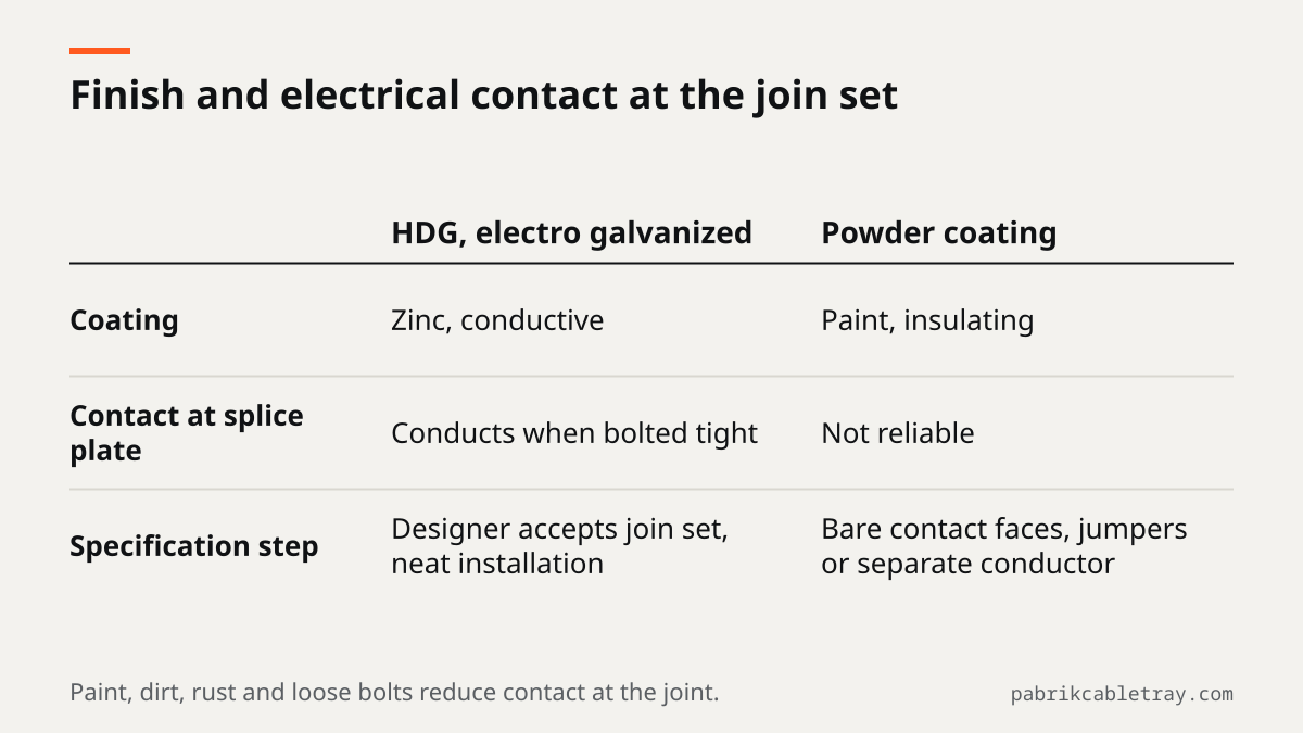
Metal to metal contact that is tightened firmly can conduct current. The quality of that joint depends on several conditions on site:
- Finish. The zinc layer of hot dip galvanized and electro galvanized finishes is conductive. Powder coating is a paint layer that acts as an insulator, so contact at the joint cannot be relied on without an additional step.
- Clean contact surfaces. Paint, dirt or rust between the plate and the rail reduces contact.
- Bolt tightness. Bolts that loosen after cable pulling make the contact unstable.
- Type of joint. A join set that locks two straight lengths is different from a joint designed to move or to set a variable angle.
So a join set can be enough on a straight galvanized run, provided the designer accepts it and the installation is done properly. At other points, the specification needs to call for an additional connection.
When bonding jumpers are needed
A bonding jumper is a flexible conductor that bridges two metal parts so that current still has a path, even when the mechanical joint does not give reliable contact. The points usually discussed in a specification:
- Expansion joints. These joints are deliberately made to slide so that long runs are not stressed as they expand and contract. A sliding joint cannot be relied on as an electrical contact, so install a bonding jumper long enough to follow the movement.
- Adjustable joints and changes of angle. Adjustable vertical and adjustable horizontal fittings are variable angle joints, while fish plates are used for horizontal and vertical joints at changes of angle. Ask the designer to state whether these points get a jumper.
- Gaps in the route. At wall penetrations, at gaps between two segments that are not spliced, or where the route changes from cable ladder to cable tray with an incomplete joint.
- Painted finishes. On powder coated routes, for example colored fire alarm routes, continuity through the splice plates cannot be relied on. The designer decides whether contact surfaces are kept free of paint, a jumper is installed at every joint, or a separate conductor is run.
- Transitions to equipment. Route ends at panels, transformers or equipment racks are bonded to the grounding system as shown on the drawings.
The number of jumpers, the conductor size and the spacing of bonding points follow the project's grounding system design. Those figures cannot be taken from a tray catalog.
Who sets the bonding spacing
The electrical designer or consultant sets the tray's role, the bonding points and the conductor size in the drawings and the specification. The MEP contractor translates them into shop drawings, counts the quantities in the BOQ and installs them. The tray supplier provides tray, fittings, join sets and supports as ordered.
If the specification is silent on grounding, the contractor should raise a technical query with the consultant before the shop drawings are approved. Do not wait for testing and commissioning, because installing jumpers on a route already full of cable is much more difficult.
The article on the NEMA VE 1 standard also includes grounding and electrical continuity between joints in the list of items to check in a project specification, together with load class, material and finish.
Specification and BOQ checklist
Use this list when you draft or review a cable route specification:
- Role of the tray. State it clearly: the tray is grounded only, bonded to a separate conductor, or the tray is used as the equipment grounding conductor.
- Grounding conductor. If there is a separate conductor along the tray, state its type, size and how it is bonded to the tray.
- Straight joints. State whether a join set with tightened bolts is considered enough, or whether every joint still gets a jumper.
- Mandatory bonding jumper points. Expansion joints, adjustable joints, gaps in the route, wall penetrations and transitions between systems.
- Finish. State the finish per area. For powder coated routes, state how continuity is maintained.
- Bonding points to the grounding system. At route ends, at panels and at other points shown on the drawings.
- Testing. State that route continuity is tested before handover and who records the results.
- Separate BOQ items. Bonding jumpers, ground clamps, grounding conductors and their terminals are written as their own lines, together with the party that supplies them.
The last point keeps these items from disappearing from the order. A standard tray accessory list includes, among others, join sets, fish plates, supports, hold down clamps, covers and bolts. If jumpers and conductors are not listed separately, nobody may end up ordering them.
Impact on product selection
Choosing cable tray or cable ladder does not change the principles above. What changes is the number of joints and fittings on the route, because every bend, branch and transition adds a point to check. How to count join sets per route is explained in the article on cable tray accessories.
The finish has a more direct effect. HDG and electro galvanized finishes keep metal contact at the joints, while powder coating needs an additional decision. If color is used to identify routes, discuss the grounding method together with the color selection.
Request a quotation to your specification
Send your route drawings, BOQ or technical specification through the contact page. Include the specification sections on grounding and finish, so that the quotation for tray, fittings, join sets and supports matches the route to be installed, and the items outside the tray supply are clear from the start.
Frequently asked questions
Can cable tray be used as the equipment grounding conductor?
Yes, if the project's electrical designer decides so and continuity is maintained at every joint. Other projects run a separate grounding conductor and only bond the tray to it. The choice must be written in the specification, not decided on site.
When is a bonding jumper needed at an expansion joint?
The specification needs to call for a bonding jumper at every expansion joint, because that joint is made to slide and cannot be relied on as an electrical contact. The jumper must be long enough to follow the movement without being pulled tight. Its type and size follow the project's grounding system design.
Who sets the bonding spacing, the contractor or the consultant?
The electrical designer or consultant sets the bonding points and spacing in the drawings and the specification. The contractor applies them in the shop drawings, the BOQ and the installation. If the specification does not mention them, the contractor should raise a technical query before the shop drawings are approved.
Does powder coated cable tray need special treatment for grounding?
Yes. The paint layer acts as an insulator, so contact at the splice plates cannot be relied on. The designer decides whether contact surfaces are kept free of paint, every joint gets a jumper, or a separate grounding conductor is run.
Are bonding jumpers part of the standard cable tray accessories?
The standard accessory list includes, among others, join sets, fish plates, supports, hold down clamps, covers and bolts. List bonding jumpers, ground clamps and grounding conductors as separate items in the BOQ, and ask in your request for quotation who supplies them.